THE RETRACTABLE WING AIRCRAFT

Compiler's words:
I should be very much thankful to the IIT students, without them it is not possible to me for here.
MOTIVE
The design is a good
example of creativity and innovation. There was good amount of
discussion on and after much deliberation on the advantages of a retractable wing aircraft during the early phase
the project started. The substantial
advantages of such a configuration are enumerated below:
The advantages – Wings Extended
- During take-off,
a large wing span enables take-off from a short runway
because of higher lift even at slow speeds.
-
Extended wings provide high lift mid-air too, which can be utilized in
passenger planes which have a high
payload.
-
Extended wings can provide sufficient lift for the plane at extremely high
altitudes where the low air density can, otherwise, hardly provide
sufficient lift. This virtue is just the one required for
bombers or stealth planes, which need
to be away from the range of enemy radars.
Contracted wings save a lot of parking
space and hence the plane can be
parked at places where providing
space is a problem.
This need is apparent in navy where many planes are required to be
accommodated in a small area.
Mid-air, at a constant altitude, the objective is to minimize the drag which can be achieved by a smaller wingspan. The reduced wingspan, yet, continues to provide the lift just sufficient to counter-balance the weight. Lower drag results in lesser fuel consumption and hence a higher fuel efficiency.
A
lower wingspan means a lower moment of inertia about the roll axis. And lower moment of inertia results in
higher maneuverability, the apt
requirement for mid-air fighters. Mid-air fighters need to roll, yaw and pitch
faster for higher freedom in movement.
The
only apparent disadvantage or limitation is that the mechanism
is expensive and otherwise difficult to implement.
Making
of variable span
As it has been introduced the
unique feature implemented in the
model is that of a variable wing
span.
Let
us throw more light on the feature.
To implement the mechanism
there were two choices- either to keep the outer part
of the wing hollow
and the inner one solid or vice-versa. We chose to go by the
former since the load on the tips is
less than at the root. The inner part of the wing is not strictly solid, as it is a skeleton structure
ribbed all across its span, but the outer part is a hollow shell
made up of 1 mm balsa strips
stiffened by chart paper over it.

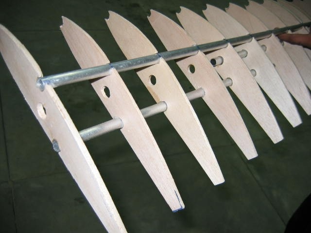
Across the inner part of
the wing three holes were cut across
to carry three Aluminum pipes: one as
a pure stiffener, and rest two
both as stiffeners and guides. The inner pipe, which is free to slide through an outer pipe just fitting in the hole, holds
the trailing end of the hollow part whereas the outer pipe holds the closer
end.
A strong string passes through
the centre of the inner pipe and is wound over
a drum attached to servo motor fitted into a box in the central part of the wing. As the motor
winds the string over the drum, it
pulls the trailing end of the wing and
the hollow outer part slides over the inner part. The accuracy is ensured by the sliding in of the inner pipe which always remains inside the
outer pipe.

For
the other way, i.e. extension, spring back is needed
which cannot be provided
by the string itself as it would just go slack. Hence a series of 11 springs for
either side were used, over the inner pipe, to provide
a spring back to the extended wingspan.
Therefore as the string relaxes the springs regain their original length,
pushing the hollow outer part to the extremities.
FLIGHT REPORT
The Retractable wing Aircraft successfully flew in its very first flight, for about a minute but nothing
comes as easy as melting ice-cream. In
the first flight we could figure out that there was some problem in fuel
supply, fuel tank was not mounted properly. Stopper in the nose landing gear was not able to withstand the impact force during landing as a
result nose landing gear collapsed
after first flight. These problems were resolved till some extent before second flight. The second flight was trouble free than the first
one. Both these flights took place at the IIT Kanpur air-strip on February 25th, 2005. The very day, and the following day, it was exhibited in Endeavour.
A picture from flight day is enclosed henceforth and the flight video is available on the website separately.
Problems encountered in the making
- A
migration from theory to reality implies a lot of approximation and an approximation means a risk in flight.
At every stage
there was a challenge of how
much approximation to minimize the risk and make the outcome predictable.
- Lack of availability of material at the right time was a problem that was faced whole throughout the making. Ultimately the plans had to
be suitably modified to compromise
with the situation and availability of material/tools.
- Since the airfoil section
was hand-cut and filed, all the ribs never aligned upon each other. Another
reason responsible for this lack of uniformity
was the fact that the reference airfoil made of plywood got filed itself the
more it was used.
It
was a hard task to guide them all by
the Aluminium pipes. The
portion of the ribs which were
mistakenly filed more had to
be filled with adhesive and the protruding ones had
to
be further filed.
Overall it took many days to bring them into alignment and proceed further.
-
The springs used in the variable part had to be determined with precision to enable exact calculation of the possible relaxation and contraction in the series.
Unfortunately there was no way to determine
precisely their exact spring
constants and hence all displacement in the wing had to be worked out
experimentally and approximately.
-
It was a big question to choose the material
for the outer hollow part. As the outer part was expected to take
the shape of the air-foil, the
material should have been flexible enough for such to happen. At the same time it should be strong and
rigid to withstand air flow over it.
Our first choice was that of a wire-mesh, with
a monocoat over it. There were two problems we encountered
with this arrangement: first of all,
it was difficult to stick the
monocoat on the mesh properly, and secondly the mesh never took the proper
shape onto the inner solid portion
when it slid over it, hence changing
the airfoil.
-
There were two portions of the fuselage joined together. Amazingly the two portions seemed perfectly symmetric. But when they were joined to form a single part, the assembly seemed unsymmetric.
It took many days to resolve
the problem and the depth of the problem was concealed behind geometrical arrangements.
- The guide rod of the ailerons
should be exactly
parallel to the pitch axis.
Also, the hinges supporting the aileron must be
protruding equidistantly from their centre and must be at the same relative height. Unfortunately on the left part of the wing
an extremely slight
error of displacement from the centre occurred, due to
which there was a huge deviation of
the guide rod from rotation about an axis passing through itself, to a description of a cone.
- The thrust vector should pass through the Fuselage Reference
Line. It was a
hard task to put the engine into
proper alignment so that the mentioned
happens.
Future prospects
The
mechanism we have implemented for wing contraction and extension
is that of a string-spring over a pulley, but the mechanism is
neither highly trustworthy nor
foolproof. Presently under
consideration is the implementation of a lead-screw mechanism whereby a lead passes inside a screw. A
further implementation could be use of stepper motors rather than servo motors since they are more precise. Another
possible option is the implementation of a rack and pinion mechanism instead of
using a spring-string couple.
Compiler's words:
I should be very much thankful to the IIT students, without them it is not possible to me for here.


No comments:
Post a Comment